Hello, guys today I am going to teach you How to make a Relay module with Optocoupler. Here I will explain everything to make a perfect relay module with an optocoupler.
All are we know the applications of relay module. When we make any smart project on home appliances, that time we use relay module most of the time. So if we are going to buy relay module form the local or online market, we have to pay huge amount of price according to home made relay module. So this article will helps you to make a sucessfull relay module witrh optocoupler.
Here you will get electronics related all information and electronics project making ideas with full guide.
If you want to see to make by me just comment down below I will definitely make for you guys.
Components list of making a Relay module with Optocoupler
Table of Contents
| SL NO | Components | Buying link |
|---|---|---|
| 1 | Relay | Buy |
| 2 | 1k resistance | Buy |
| 3 | 330 Ohm resistance | Buy |
| 4 | 817 Optocoupler | Buy |
| 5 | 4007 Diode | Buy |
| 6 | BC547 Transistor | Buy |
| 7 | Male Headers pins | Buy |
| 8 | RED LED and Green LED | Buy |
| 9 | Vero Board | Buy |
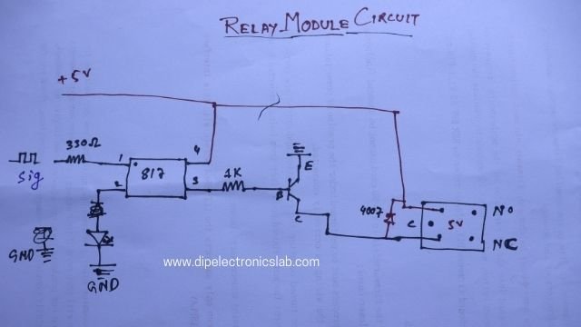
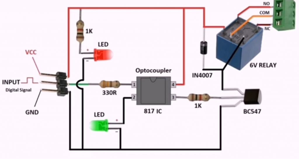
Circuit diagram of Relay Module with Optocoupler
Relay module Making Process
Now I am going to tell you how you can make relay module with just three simple step at your home. just follow the below three steps and make your relay module very easilly.
First Step to make a relay module with Optocoupler
The first step, you have to do is, Insert all the required components inside the Vero PCB. I have attached the picture of insert all the needed components to make a relay module. Scroll down and see that image of how to insert all the components.

Second Step to make a Relay module with Optocoupler
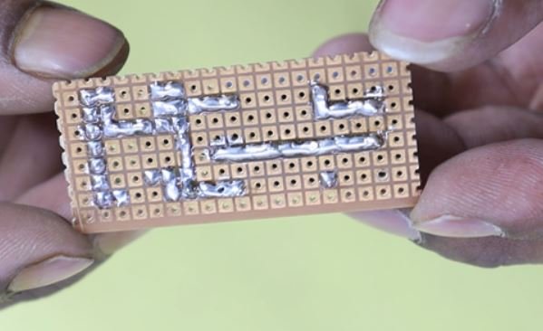
In the second step, you have to solder all the components legs with the Vero board. I have attached a picture below of this block. See that picture and know how you have to solder all the component’s legs.
Final Step to make a Relay Module with Optocoupler
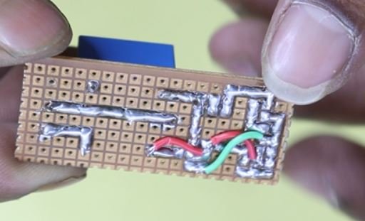
In the final step, you have to connect all the components to each other according to the circuit diagram. I already provide you the circuit diagram of the relay module with optocoupler. See that picture and connect all the components with each other to execute the relay module circuit. I have attached an image to know the connection of all the components to each other.
The project is completed, now you can use this Relay module to your smart home project to control the home appliances. I have attached a video tutorial on how to make a relay module with optocoupler in the below of this block, just scroll down and watch that video.
Related post of making Relay Module with optocoupler
- LCD LED Repairing guide Ebook
- How to make Pixel LED Controller Circuit Board
- How to make ATtiny Shield
- How to Upload Code on Any Attiny IC
- What is Bootloader in Electronics
- Best Android TV Box in India
- LCD LED Repairing Practical Video
Watch video of making Relay Module with Optocupler
FAQ of making Relay Module with Optocoupler
How do you make a relay module circuit?
It is very easy to make a Relay module circuit. in this post, I have explained how you can make a relay module circuit with an optocoupler step by step. If you want to know the circuit-making process of the relay module, read this article very carefully step by step.
Needed Components to make A Relay Module
1. 1k resistance
2. 330 Ohm resistance
3. 817 Optocoupler
4. 4007 Diode
5. BC547 Transistor
6. Male Headers pins
7. RED LED and Green LED
8. Vero Board
9. Relay
How do you make a 12V relay module?
To make 12v relay module circuit just change the relay and add a 7805 voltage regulator to provide 5v to the optocoupler input section. To know more information about 12v relay module read this article very carefully.
How do you build a 4 channel relay board?
To build a 4 channel relay module do the same thing which you do for making one channel relay module. Just you have to do connect all the positive(+) and the Negative (-) terminal with all the circuits. just input signal terminal will be different for all the four relay module circuits. To know more information about this relay module circuit read this post very carefully, I have explained everything about making a relay module.


